Use Case Diagram
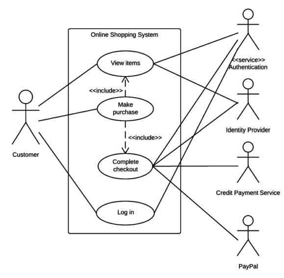
Use Case Diagram in Unified Modeling Language (UML) is a visual representation that illustrates the interactions between users (actors) and a system. It captures the functional requirements of a system, showing how different users engage with various use cases, or specific functionalities, within the system. Use case diagrams provide a high-level overview of a system’s behavior, making them useful for stakeholders, developers, and analysts to understand how a system is intended to operate from the user’s perspective, and how different processes relate to one another. They are crucial for defining system scope and requirements.
Use case diagram notations
UML notations provide a visual language that enables software developers, designers, and other stakeholders to communicate and document system designs, architectures, and behaviors in a consistent and understandable manner.
Actors
Actors are external entities that interact with the system. These can include users, other systems, or hardware devices. In the context of a Use Case Diagram, actors initiate use cases and receive the outcomes. Proper identification and understanding of actors are crucial for accurately modeling system behavior.
Use cases
Use cases are like scenes in the play. They represent specific things your system can do. In the online shopping system, examples of use cases could be “Place Order,” “Track Delivery,” or “Update Product Information”. Use cases are represented by ovals.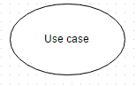
System boundary
The system boundary is a visual representation of the scope or limits of the system you are modeling. It defines what is inside the system and what is outside. The boundary helps to establish a clear distinction between the elements that are part of the system and those that are external to it. The system boundary is typically represented by a rectangular box that surrounds all the use cases of the system.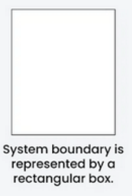
Use case diagram relationships
In a Use Case Diagram, relationships play a crucial role in depicting the interactions between actors and use cases. These relationships provide a comprehensive view of the system’s functionality and its various scenarios. Let’s delve into the key types of relationships and explore examples to illustrate their usage.
Association relationship
The Association Relationship represents a communication or interaction between an actor and a use case. It is depicted by a line connecting the actor to the use case. This relationship signifies that the actor is involved in the functionality described by the use case.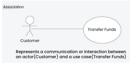
Include relationship
The Include Relationship indicates that a use case includes the functionality of another use case. It is denoted by a dashed arrow pointing from the including use case to the included use case. This relationship promotes modular and reusable design.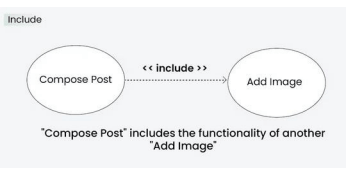
Extend relationship
The Extend Relationship illustrates that a use case can be extended by another use case under specific conditions. It is represented by a dashed arrow with the keyword “extend.” This relationship is useful for handling optional or exceptional behavior.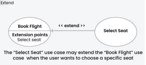
EXAMPLE