The Design Model
Process and abstraction dimensions
Analysis viewed in two different dimensions as process dimension and abstract dimension.
Process dimension indicates the evolution of the design model as design tasks are executed as part of software process.
Abstraction dimension represents the level of details as each element of the analysis model is transformed into design equivalent.
Data design elements
Data design creates a model of data that is represented at a high level of abstraction.
Refined progressively to more implementation-specific representation for processing by the computer-based system.
Translation of data model into a database is pivotal to achieving business objective of a system.
Data design elements description
It creates a model of data and/or information that is represented at a high level of abstraction (the customer/user’s view of data). This data model is then refined into progressively more implementation-specific representations that can be processed by the computer-based system.
In many software applications, the architecture of the data will have a profound influence on the architecture of the software that must process it.
The architectural design elements
The architectural design for software is the equivalent to the floor plan of a house. The floor plan depicts the overall layout of the rooms; their size, shape, and relationship to one another; and the doors and windows that allow movement into and out of the rooms. The floor plan gives us an overall view of the house. Architectural design elements give us an overall view of the software.
It is derived from three sources:
(i) Information about the application domain for the software to be built;
(ii) Specific requirements model elements such as data flow diagrams or analysis classes, their relationships, and collaborations for the problem at hand; and
(iii) The availability of architectural styles and patterns.
Interface design elements
The interface design for software is analogous to a set of detailed drawings (and specifications) for the doors, windows, and external utilities of a house. These drawings depict the size and shape of doors and windows, the manner in which they operate, the way in which utility connections (Example: water, electrical, gas, telephone) come into the house and are distributed among the rooms depicted in the floor plan.
Important elements of interface design
(i) The user interface (UD);
(ii) External interfaces to other systems, devices, networks, or other producers or consumers of information; and
(iii) Internal interfaces between various design components.
Component-level design elements
The component-level design for software is the equivalent to a set of detailed drawings (and specifications) for each room in a house. These drawings depict wiring and plumbing within each room, the location of electrical receptacles and wall switches, faucets, sinks, showers, tubs, drains, cabinets, and closets. They also describe the flooring to be used, the moldings to be applied, and every other detail associated with a room. The component-level design for software fully describes the internal detail of each software component.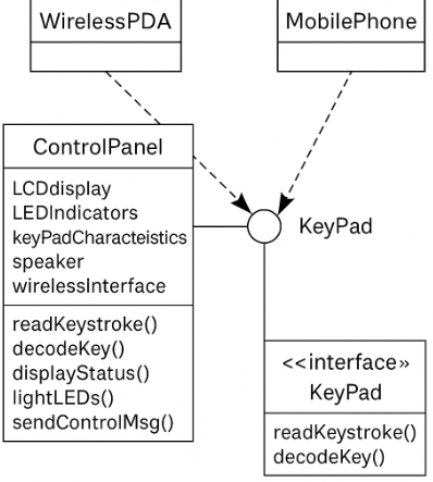
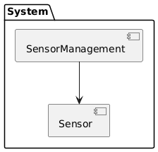
Deployment level design elements
Deployment level design elements indicate how software functionality and subsystems will be allocated within the physical computing environment that will support the software. For example, the elements of the Safe Home product are configured to operate within three primary computing environments – a home-based PC, the Safe Home control panel, and a server housed at CPI Corp. (providing Internet-based access to the system.