Sequence Diagram
A Sequence Diagram is a key component of Unified Modeling Language (UML) used to visualize the interaction between objects in a sequential order. It focuses on how objects communicate with each other over time, making it an essential tool for modeling dynamic behavior in a system. Sequence diagrams illustrate object interactions, message flows, and the sequence of operations, making them valuable for understanding use cases, designing system architecture, and documenting complex processes.
Why use sequence diagrams?
Sequence diagrams are used because they offer a clear and detailed visualization of the interactions between objects or components in a system, focusing on the order and timing of these interactions. Here are some key reasons for using sequence diagrams:
Visualizing Dynamic Behavior: Sequence diagrams depict how objects or systems interact with each other in a sequential manner, making it easier to understand dynamic processes and workflows.
Clear Communication: They provide an intuitive way to convey system behavior, helping teams understand complex interactions without diving into code.
Use Case Analysis: Sequence diagrams are useful for analyzing and representing use cases, making it clear how specific processes are executed within a system.
Designing System Architecture: They assist in defining how various components or services in a system communicate, which is essential for designing complex, distributed systems or service-oriented architectures.
Documenting System Behavior: Sequence diagrams provide an effective way to document how different parts of a system work together, which can be useful for both developers and maintenance teams.
Debugging and Troubleshooting: By modeling the sequence of interactions, they help identify potential bottlenecks, inefficiencies, or errors in system processes.
Sequence diagram notations
Actors
An actor in a UML diagram represents a type of role where it interacts with the system and its objects. It is important to note here that an actor is always outside the scope of the system we aim to model using the UML diagram.
Lifelines
A lifeline is a named element which depicts an individual participant in a sequence diagram. So basically each instance in a sequence diagram is represented by a lifeline. Lifeline elements are located at the top in a sequence diagram. The standard in UML for naming a lifeline follows the following format:
Messages
Communication between objects is depicted using messages. The messages appear in a sequential order on the lifeline.
We represent messages using arrows.
Lifelines and messages form the core of a sequence diagram.
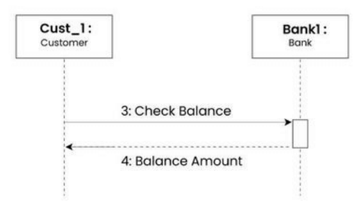
Synchronous messages
A synchronous message waits for a reply before the interaction can move forward. The sender waits until the receiver has completed the processing of the message. The caller continues only when it knows that the receiver has processed the previous message i.e. it receives a reply message.
A large number of calls in object oriented programming are synchronous.
We use a solid arrow head to represent a synchronous message.
Asynchronous messages
An asynchronous message does not wait for a reply from the receiver. The interaction moves forward irrespective of the receiver processing the previous message or not. We use a lined arrow head to represent an asynchronous message.
Create message
We use a Create message to instantiate a new object in the sequence diagram. There are situations when a particular message call requires the creation of an object. It is represented with a dotted arrow and create word labelled on it to specify that it is the create Message symbol.
Delete message
We use a Delete Message to delete an object. When an object is deallocated memory or is destroyed within the system we use the Delete Message symbol. It destroys the occurrence of the object in the system. It is represented by an arrow terminating with a x.
Self message
Certain scenarios might arise where the object needs to send a message to itself. Such messages are called Self Messages and are represented with a U shaped arrow.
Reply message
Reply messages are used to show the message being sent from the receiver to the sender. We represent a return/reply message using an open arrow head with a dotted line. The interaction moves forward only when a reply message is sent by the receiver.
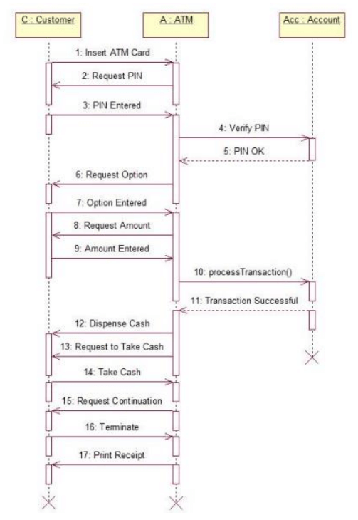
EXAMPLE