The conceptual model of UML
The conceptual model of UML contains basic building blocks along with the rules that must be followed while building those blocks together and some general mechanisms that relate all the way through the UML.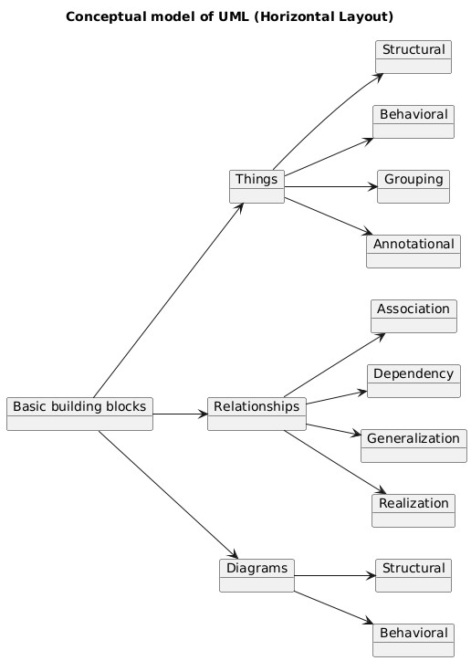
The building blocks of UML can be defined as:
1. Things
2. Relationships
3. Diagrams
Things
Things are the most important building blocks of UML. Things can be:
Structural
Behavioral
Grouping
Annotational
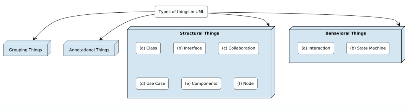
Structural things
The structural things define the static part of the model. They represent physical and conceptual elements. Following are the brief descriptions of the structural things:
Class
Class represents set of objects having similar responsibilities.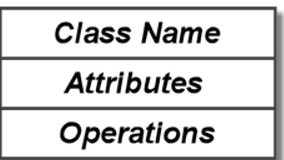
Interface
Interface defines a set of operations which specify the responsibility of a class.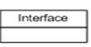
Collaboration
Collaboration defines interaction between elements.
Use case
Use case represents a set of actions performed by a system for a specific goal.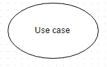
Component
Component describes physical part of a system.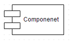
Node
A node can be defined as a physical element that exists at run time.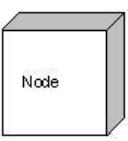
Behavioral things
A behavioral thing consists of the dynamic parts of UML models. Following are the behavioral things:
Interaction
Interaction is defined as a behavior that consists of a group of messages exchanged among elements to accomplish a specific task.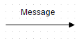
State machine
State machine is useful when the state of an object in its life cycle is important. It defines the sequence of states an object goes through in response to events. Events are external factors responsible for state change.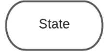
Grouping things
Grouping things can be defined as a mechanism to group elements of a UML model together. There is only one grouping thing available:
Package
Package is the only one grouping thing available for gathering structural and behavioral things.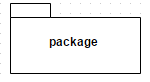
Annotational things
Annotational things can be defined as a mechanism to capture remarks, descriptions, and comments of UML model elements.
Note
A note is used to render comments, constraints etc of an UML element.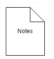
Relationships
Relationships are another most important building block of UML. It shows how elements are associated with each other and this association describes the functionality of an application.
There are four kinds of relationships available:
Dependency
Dependency is a relationship between two things in which change in one element also affects the other one.
Association
Association is basically a set of links that connects elements of an UML model. It also describes how many objects are taking part in that relationship.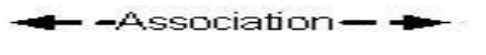
Generalization
Generalization can be defined as a relationship which connects a specialized element with a generalized element. It basically describes inheritance relationship in the world of objects.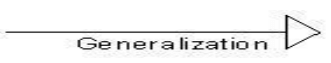
Realization
Realization can be defined as a relationship in which two elements are connected. One element describes some responsibility which is not implemented and the other one implements them. This relationship exists in case of interfaces.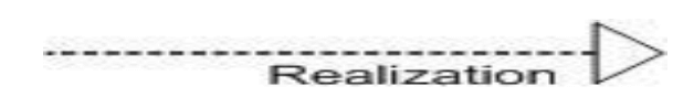
UML diagrams
UML diagrams are graphical representation of things in UML.
• They give static as well as dynamic view of system.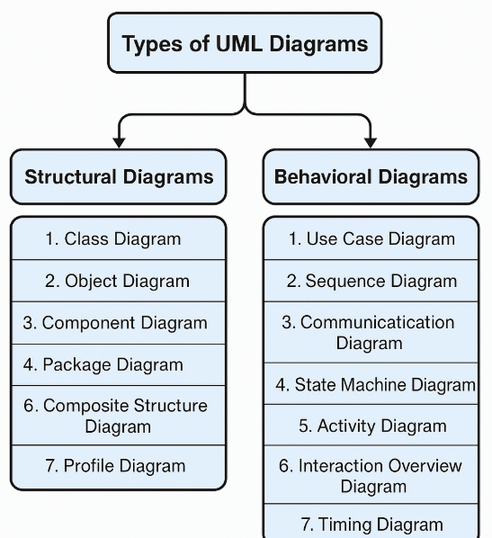
Class diagrams
Class diagrams are the most essential part of every object oriented method, including UML.
They define the fixed structure of a system. It shows a group of classes, interfaces and collaboration and their relationships.
Object diagrams
Object diagrams describe the static structure of a system at a particular time.
It shows a set of objects and their relationships. They can be used to test class diagrams for accuracy.
Use case diagrams
Use case diagrams model the functionality of system using actors and use cases and their relationships.
Sequence diagrams
Sequence diagrams describe interactions among classes in terms of an exchange of messages over time.
Collaboration diagrams
Collaboration diagrams represent interactions between objects as a series of sequenced messages.
Collaboration diagrams describe both the static structure and the dynamic behavior of a system.
State chart diagrams
State chart diagrams describe the dynamic behavior of a system in response to external stimuli.
It shows states, transitions, events and activities.
State chart diagrams are especially useful in modeling reactive objects whose states are triggered by specific events.
Activity diagrams
Activity diagrams show the dynamic nature of a system by representing the flow of control from activity to activity.
An activity represents an operation on some class in the system that results in a change in the state of the system.
Typically, activity diagrams are used to model workflow or business processes and internal operation.
Component diagrams
Component diagrams shows the organizations and dependencies among a set of components.
They describe the organization of physical software components, including source code, run-time (binary) code, and executables.
Deployment diagrams
A Deployment diagram shows the configuration of run-time processing nodes and the components that live in them.
It depict the physical resources in a system, including nodes, components, and connections.