Component Diagram
Component-based diagrams are essential tools in software engineering, providing a visual representation of a system’s structure by showcasing its various components and their interactions. These diagrams simplify complex systems, making it easier for developers to design, understand, and communicate the architecture.
Components of component-based diagram
Component-Based Diagrams in UML comprise several key elements, each serving a distinct role in illustrating the system’s architecture. Here are the main components and their roles:
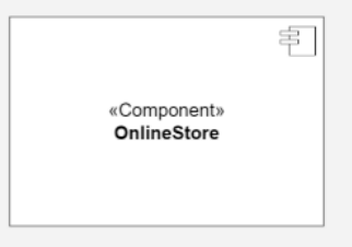
Component
Represent modular parts of the system that encapsulate functionalities. Components can be software classes, collections of classes, or subsystems.
Symbol: Rectangles with the component stereotype («component»).
Function: Define and encapsulate functionality, ensuring modularity and reusability.
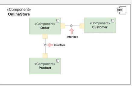
Interfaces
Specify a set of operations that a component offers or requires, serving as a contract between the component and its environment.
Symbol: Circles (lollipops) for provided interfaces and half-circles (sockets) for required interfaces.
Function: Define how components communicate with each other, ensuring that components can be developed and maintained independently.
Relationships
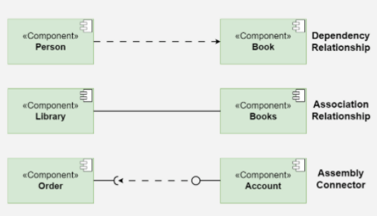
Depict the connections and dependencies between components and interfaces.
Symbol: Lines and arrows.
Dependency (dashed arrow): Indicates that one component relies on another.
Association (solid line): Shows a more permanent relationship between components.
Assembly connector: Connects a required interface of one component to a provided interface of another.
Function: Visualize how components interact and depend on each other, highlighting communication paths and potential points of failure.
Ports
Role: Represent specific interaction points on the boundary of a component where interfaces are provided or required.
Symbol: Small squares on the component boundary.
Function: Allow for more precise specification of interaction points, facilitating detailed design and implementation.
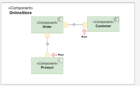
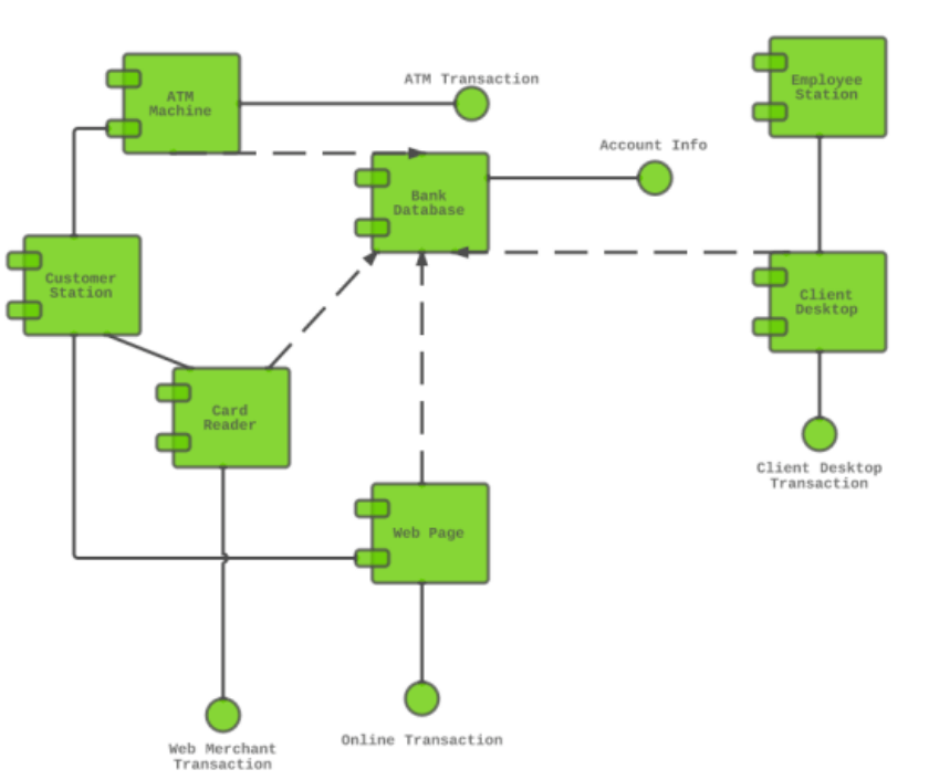
Example