Collaboration Diagrams
In UML (Unified Modeling Language), a Collaboration Diagram is a type of Interaction Diagram that visualizes the interactions and relationships between objects in a system. It shows how objects collaborate to achieve a specific task or behavior. Collaboration diagrams are used to model the dynamic behavior of a system and illustrate the flow of messages between objects during a particular scenario or use case.
Importance of collaboration diagrams
Collaboration diagrams is important for understanding communication, design, analysis, and documentation of the system’s architecture and behavior.
Visualizing Interactions:
These diagrams offer a clear visual representation of how objects or components interact within a system.
This visualization helps stakeholders in understanding the flow of data and control for easier understanding.
Understanding System Behavior:
By showing interactions, collaboration diagrams provide insights into the system’s dynamic behavior during operation.
Understanding this behavior is important for identifying potential issues, optimizing performance, and ensuring the system functions smoothly.
Facilitating Communication:
Collaboration diagrams provide an effective communication tools among team members.
They facilitate discussions, enabling refinement of the system’s design, architecture, and functionality.
Components and their notations in collaboration diagrams
There are several components in Collaboration Diagram. Let’s see those components and their notations:
Objects/Participants
Objects are represented by rectangles with the object’s name at the top. Each object participating in the interaction is shown as a separate rectangle in the diagram. Objects are connected by lines to indicate messages being passed between them.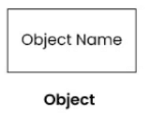
Multiple objects
Multiple objects are represented by rectangles, each with the object’s name inside, and interactions between them are shown using arrows to indicate message flows.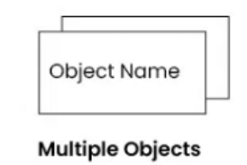
Actors
They are usually shown at the top or side of the diagram. Actors indicate their involvement in the interactions with the system’s objects or components. They are connected to objects through messages, showing the communication with the system.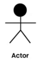
Messages
Messages represent communication between objects. Messages are shown as arrows between objects, indicating the flow of communication. Each message may include a label indicating the type of message (e.g., method call, signal). Messages can be asynchronous (indicated by a dashed arrow) or synchronous (solid arrow).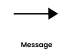
Self message
This is a message that an object sends to itself. It represents an action or behavior that the object performs internally without involving any other objects. Self-messages are useful for modeling scenarios where an object triggers its own methods or processes.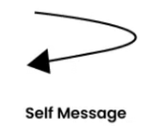
Links
Links represent associations or relationships between objects. Links are shown as lines connecting objects, with optional labels to indicate the nature of the relationship. Links can be uni-directional or bi-directional, depending on the nature of the association.
Return messages
Return messages represent the return value of a message. They are shown as dashed arrows with a label indicating the return value. Return messages are used to indicate that a message has been processed and a response is being sent back to the calling object.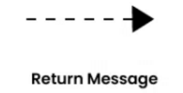
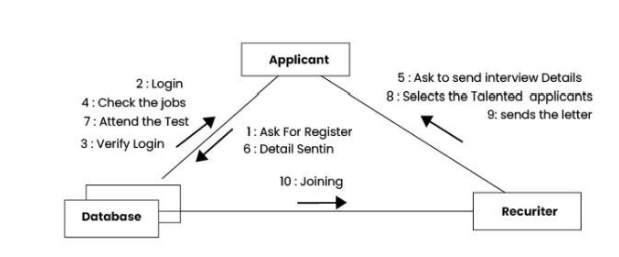
Example