Class Diagram
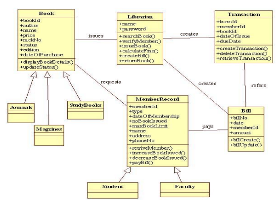
A UML class diagram is a visual tool that represents the structure of a system by showing its classes, attributes, methods, and the relationships between them. It helps everyone involved in a project—like developers and designers—understand how the system is organized and how its components interact.
Class
In object-oriented programming (OOP), a class is a blueprint or template for creating objects. Objects are instances of classes, and each class defines a set of attributes (data members) and methods (functions or procedures) that the objects created from that class will possess. The attributes represent the characteristics or properties of the object, while the methods define the behaviors or actions that the object can perform.
UML class notation
Class notation is a graphical representation used to depict classes and their relationships in object-oriented modeling.
1. Class name
The name of the class is typically written in the top compartment of the class box and is centered and bold.
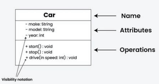
2. Attributes
Attributes, also known as properties or fields, represent the data members of the class. They are listed in the second compartment of the class box and often include the visibility (e.g., public, private) and the data type of each attribute.
3. Methods
Methods, also known as functions or operations, represent the behavior or functionality of the class. They are listed in the third compartment of the class box and include the visibility (e.g., public, private), return type, and parameters of each method.
4. Visibility notation
Visibility notations indicate the access level of attributes and methods. Common visibility notations include:
for public (visible to all classes)
for private (visible only within the class)
for protected (visible to subclasses)
~ for package or default visibility (visible to classes in the same package)
Relationships between classes
In class diagrams, relationships between classes describe how classes are connected or interact with each other within a system. There are several types of relationships in object-oriented modeling, each serving a specific purpose. Here are some common types of relationships in class diagrams:
Association
An association represents a bi-directional relationship between two classes. It indicates that instances of one class are connected to instances of another class. Associations are typically depicted as a solid line connecting the classes, with optional arrows indicating the direction of the relationship.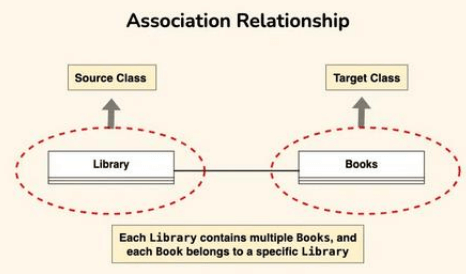
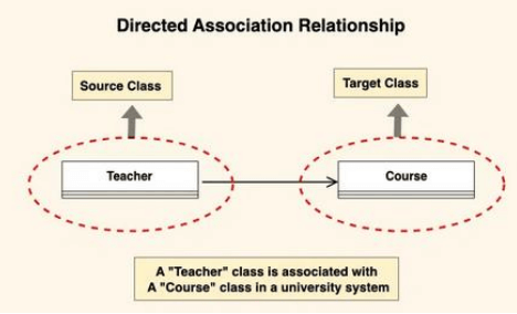
Directed association
A directed association in a UML class diagram represents a relationship between two classes where the association has a direction, indicating that one class is associated with another in a specific way.
In a directed association, an arrowhead is added to the association line to indicate the direction of the relationship. The arrow points from the class that initiates the association to the class that is being targeted or affected by the association.
Directed associations are used when the association has a specific flow or directionality, such as indicating which class is responsible for initiating the association or which class has a dependency on another.
Aggregation
Aggregation is a specialized form of association that represents a “whole-part” relationship. It denotes a stronger relationship where one class (the whole) contains or is composed of another class (the part). Aggregation is represented by a diamond shape on the side of the whole class. In this kind of relationship, the child class can exist independently of its parent class.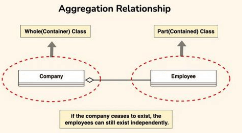
Composition
Composition is a stronger form of aggregation, indicating a more significant ownership or dependency relationship. In composition, the part class cannot exist independently of the whole class. Composition is represented by a filled diamond shape on the side of the whole class.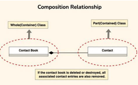
Generalization (inheritance)
Inheritance represents an “is-a” relationship between classes, where one class (the subclass or child) inherits the properties and behaviors of another class (the superclass or parent). Inheritance is depicted by a solid line with a closed, hollow arrowhead pointing from the subclass to the superclass.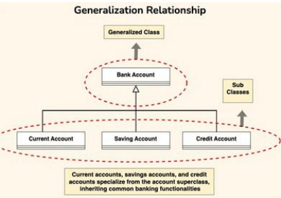
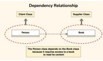
Dependency relationship
A dependency exists between two classes when one class relies on another, but the relationship is not as strong as association or inheritance. It represents a more loosely coupled connection between classes. Dependencies are often depicted as a dashed arrow.
Let’s consider a scenario where a Person depends on a Book:
Person Class: Represents an individual who reads a book. The Person class depends on the Book class to access and read the content.
Book Class: Represents a book that contains content to be read by a person. The Book class is independent and can exist without the Person class.
Purpose of class diagrams
The main purpose of using class diagrams is:
This is the only UML that can appropriately depict various aspects of the OOPs concept.
Proper design and analysis of applications can be faster and efficient.
It is the base for deployment and component diagram.
It incorporates forward and reverse engineering.
Advantages of class diagrams
Below are the benefits of class diagrams:
Class diagrams represent the system’s classes, attributes, methods, and relationships, providing a clear view of its architecture.
They shows various relationships between classes, such as associations and inheritance, helping stakeholders understand component connectivity.
Class diagrams serve as a visual tool for communication among team members and stakeholders, bridging gaps between technical and non-technical audiences.
They guide developers in coding by illustrating the design, ensuring consistency between the design and actual implementation.
Many development tools allow for code generation from class diagrams, reducing manual errors and saving time.