Structured Methods
Introduction
Structured methods are used to generate models in an organized manner. These methods find their applications in the requirements elucidation and analysis phase of the software development process. They provide a core framework that can be successfully applied in developing detailed and specifically large models.
Structured methods consist of a set of processes and rules/regulations adhering to which sophisticated models are developed. These methods also produce standard documents for the system.
They encompass several CASE tools (Computer-Aided Software Engineering tools) which can be effectively used for:
Modifying existing models
Developing code
Generating reports
Validating available models to some extent
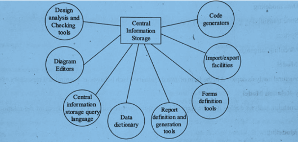
Components of CASE Tools
A brief illustration of these CASE tools is given below:
1. Code Generators
Automatically generate code or code format based on information available in the central information storage.
2. Import/Export Facilities
Allows the transfer of data to and from the central storage and external sources.
3. Form Definition Tools
Define formats or specifications for developing reports or forms, and for structuring data on the screen.
4. Reports Definition and Generation Tools
Automatically generate documents using data from the central storage.
5. Data Dictionary
Stores large volumes of system-related entity information in an organized way.
6. Central Information Storage Query Language
Allows users to retrieve design information stored in central storage using queries.
7. Diagram Editors
Help generate various models (behavioral, object-data models, etc.) and store related information in the central storage.
8. Design Analysis and Checking Tools
Used to evaluate reports and documentation, and to identify errors.
Models Used for Structured Analysis
Structured methods use the following modeling approaches:
1. Data Model
Used as a data dictionary in structural analysis.
Acts as a centralized repository of data and objects.
2. Entity-Relation Model
Represented using an ER diagram.
Helps understand relationship types and nature among entities.
3. Data Modeling
Deployed using data structure diagrams.
Represents how data is stored in terms of structure and attributes.
4. Data Flow
Represented using a Data Flow Diagram (DFD).
Shows how data flows through various functions of the system.
5. State Transition Model
Represented as process flow charts.
Shows how system functions behave under the influence of external stimuli.
6. System Model
Visualized using system flow diagrams.
Describes system context, position, and interfaces.
7. Modeling Language
Provides diagramming notations for representing entities, process flows, storage, decisions, and visual models.