Procedure: (I) Problem Statement
The Software Personnel Management System allows employees to record time cards electronically and automatically generates pay slips based on the number of hours worked and total amount of sales. The system will run on individual employee desktops, where the employee can access and edit only their personal details. The system will maintain information on the employees in the company to calculate payroll. Employees will also be able to know from the system the number of hours worked per day, the total of all hours spent on a project, and the total pay received year-to-date, etc. Payroll administrators keep track of all the information, including adding new employees, deleting employees, editing information, and running reports. The system will generate records and performance reports of the employees.
(II)Software Requirement Specification:
Introduction
The Software Personnel Management System is an interface between the employee and the administrator responsible for the generation of payment slips. It aims at improving the efficiency in the generation of pay slips and reduces the complexities involved in it to the maximum possible extent.
Purpose
If the entire process of Software Personnel Management is done manually, it would take more time for the pay slip generation process. Considering the fact that the number of employees is increasing every year, a maintenance system is essential to meet the demand. This system uses several programming and database techniques to elucidate the work involved in this process.
Scope
- The software system allows the administrator to manage employees in a better way.
- When needed, it will take just a few seconds to find out the background of an employee and his/her contribution to the organization, facilitating the keeping of all employee records.
- All information about an employee will be available in a few seconds, making it easy to generate statistical data or custom data, such as finding a certain set of employees.
Overall Description
Product Perspective:
The SPMS acts as an interface between the ‘Administrator’ and the ‘Employee’. This system tries to make the interface as simple as possible while ensuring the security of the data stored. This minimizes the time duration required to manage the software personnel.
Software Interface
- Front End Client: The applicant and administrator online interface is built using JSP and HTML. The administrator’s local interface is built using Java.
- Web Server: Apache Tomcat application server (Oracle Corporation).
- Back End: Oracle 11g database.
Hardware Interface
The server is directly connected to the client systems. The client systems have access to the database on the server.
System Functions
The payment module greatly reduces the workload of the administrator department by automating the payroll process, allowing the administrator to ensure that payroll functions are completed on time and without errors. The payroll class automatically calculates payment amounts and various deductions, such as income tax, before generating paychecks and employee tax reports.
Definitions, Acronyms, and Abbreviations
- Administrator: Refers to the super user who is maintaining employee details.
- Employee: One who works for a software company.
- SPMS: Refers to the Software Personnel Management System.
- HTML: Markup Language used for creating web pages.
- J2EE: Java 2 Enterprise Edition, a programming platform for developing and running distributed Java applications.
- HTTP: Hypertext Transfer Protocol.
References
- IEEE Software Requirement Specification format.
Technologies to Be Used
- HTML
- JSP
- JavaScript
- Java
- XML
- AJAX
Tools to Be Used
- Eclipse IDE (Integrated Development Environment)
- Rational Rose tool (for developing UML patterns)
Overview
The Software Requirements Specification (SRS) includes two sections: overall description and specific requirements.
- Overall Description will describe the major roles of the system components and their interconnections.
- Specific Requirements will describe the roles and functions of the actors.
View Salary
The employee views the salary details efficiently from the SPMS. Employees will also be able to know from the system the number of hours worked per day, the total of all hours spent on a project, and the total pay received year-to-date, etc.
User Characteristics
- Employee: These are the persons who desire to view the salary details.
- Administrator: The administrator has certain privileges to generate pay slips for the employees.
- Database Manager: The DB manager stores all the data related to employees and administrators.
Constraints
- The administrator requires a system to monitor information about the employees.
Assumptions and Dependencies
- The employee and administrator must have basic knowledge of computers and the English language.
(III) Use Case Diagram
The Software Personnel Management System use cases are:
- Login
- Job Assigned
- View Salary
- View Employee Details
- Generate Payment Slip
- Create DB
- Update DB 8
- Delete DB
Actors involved:
- Employee
- Administrator
Data base Manager
Use-Case name: Login
The Employee log into the system to view the salary details
Use-Case name: Job Assigned
The employee views the job assigned to him/ herby the Administrator.
Use-Case name: View salary
The employee views the salary details efficiently from the SPMS. The employees will also be able to know the number of hours worked per day and total of all hours spent on a project and total pay received year-to-date etc.
Use-Case name: View employee details
The Administrator views the details of the employee for the pay roll process
Use-Case name: Generate payment slip
The Administrator generates the pay slip based on the details of the no of hours/no of days worked by the employee.
The Administrator generates the pay slip based on the details of the no of hours/no of days worked by the employee.
Use-Case name: Create Db
The data base manager creates individual data base tables for the employees
Use-Case name: Update db
When employee information changes the data base manager updates individual data base tables for the employees.
Use-Case name: Delete db
When an employee relieves/terminated the data base manager deletes individual data base tables for the employees.

Activity Diagram:
The activity diagram notation is an action, partition, fork join and object node. Most of the notation is self explanatory, two subtle points. Once an action finished, there is an automatic outgoing transaction. The diagram can show both control flow and dataflow.

Class Diagram:
The class diagram is referred as object modeling in the static analysis diagram. The main task of object modeling is to graphically show what each object will do in the problem domain. The problem domain describes the structure and the relationships among objects.
The Software Personnel Management system class diagram consists of four classes
- Employee class
- Administrator class
- Data base Manager class
- Payment class
1.Employee class
It consists of seven attributes and two operations. The attributes are EMP id, EMP name, EMP password, address, mobile number, date, Hours Worked. The operations of this class are Login () and view salary ( ).
2.Administrator class
It consists of attributes Admin id, Admin name and Admin password. The operations are login (), Generate pay roll (), view payroll () and view employee detail ( ).
3.Database manager class
The attributes of this class are DB manager id, DB manager name () and DB manager password. The operation are create ( ), update ( ), delete ( ) and display pay roll ( ).
4.Payment class
The attributes of this class are payment id, EMP id, date, Basic pay, HRA, DA, PF, Net pay and Gross pay. The operation are calculate salary () and Generate Slip ().

Management system
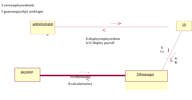
Interaction Diagram:
- A sequence diagram represents the sequence and interactions of a given USE- CASE or scenario .Sequence diagram scan capture most of the information about the system. Most object to object inter actions and operations are considered events and events include signals,
- inputs, decisions, interrupts transitions and actions to or from users or external devices.
- An event also is considered to be any action by an object that sends
- The event line represents a message sent from one object to another ,in which the “form” object is requesting an operation be performed by the “to” object.
- The “to” object performs the operation using a method that the class
- It is also represented by the order in which things occur and how the objects in the system send message to one another.
- The sequence diagram for each USE-CASE that exists when a user administrator, check status and new registration about passport automation system are given.


State Transition Diagram
- States of object are represented as rectangle with round corner, the transaction between the different states.
- A transition is a relationship between two state that indicates that when an event occur the object moves from the prior state to the subsequent.

Deployment Diagram and component Diagram
Deployment diagrams are used to visualize the topology of the physical components of a system where the software components are deployed

Component Diagram
Component diagrams are used to visualize the organization and relationships among components in a system.
